
Objetivo
Neste projeto faremos uma aplicação utilizando o kit STM32F0Discovery para imprimir caracteres em um display LCD alfanumérico 16×4.
Materiais
Serão necessários:
- Kit STM32F0Discovery;
- Display LCD 16×2 ou 16×4 com controlador HD44780, KS0066 ou SPLC780D1;
- Protoboard;
- Trimpot de 10k Ohm;
- Jumpers.
Neste projeto está sendo utilizado o display LCD modelo AGM 1604A-801 (azul – 16×04).
Esquema de conexão
A conexão entre a Discovery e o display é dada da seguinte forma:

Ferramentas
Para agilizarmos o desenvolvimento deste projeto, faremos o uso do STM32CubeMX, ferramenta já apresentada no artigo “Crie projetos com o STM32Cube“. Neste, o projeto exemplo tem como base o mesmo kit deste artigo. Assim, inicializaremos um novo projeto no STM32CubeMX da mesma forma que foi feito, porém com algumas ressalvas: depois que realizar as configurações necessárias, a ferramenta “alvo” para o desenvolvimento da aplicação será o MDK-ARM v5, esta opção é feita através de “Project Settings/Project/Toolchain IDE”.
Antes de pressionar “OK” para gerar o projeto, escolha a opção “Copy only the necessary library files”, assim, serão gerados somente arquivos pertinentes aos periféricos ativados e para escolher esta opção, realize o seguinte caminho: “Project Settings/Code Generator/STM32Cube Firmware Libray Package” (figura 2).

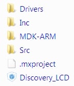
Depois de escolhido o diretório para salvar o projeto STM32CubeMX e pressionado o botão “OK”, abra este mesmo diretório para visualizar os arquivos, cujos conteúdos podem ser vistos conforme a figura 3.
Abra o arquivo do projeto MDK-ARM v5 com a extensão .uvprojx para iniciarmos a ferramenta (uVision 5) e, consequentemente, a escrita do código da aplicação.
Código
O código fonte do driver para controlar e escrever no display LCD, pode ser visto a seguir:
/*
 *
 *		LCD driver for STM32F051R8T6 microcontroller.
 *
 *
 */
#include "LCD.h"
#include "stm32f0xx_hal_gpio.h"
#include "Delay.h"

/*----------------------------------------------------------
 * UserFont: characters to be loaded into CGRAM.
 *
 *---------------------------------------------------------*/
const char UserFont[8][8] = {
    { 0x00,0x00,0x00,0x00,0x00,0x00,0x00,0x00 },
    { 0x10,0x10,0x10,0x10,0x10,0x10,0x10,0x10 },
    { 0x18,0x18,0x18,0x18,0x18,0x18,0x18,0x18 },
    { 0x1C,0x1C,0x1C,0x1C,0x1C,0x1C,0x1C,0x1C },
    { 0x1E,0x1E,0x1E,0x1E,0x1E,0x1E,0x1E,0x1E },
    { 0x1F,0x1F,0x1F,0x1F,0x1F,0x1F,0x1F,0x1F },
    { 0x00,0x00,0x00,0x00,0x00,0x00,0x00,0x00 },
    { 0x00,0x00,0x00,0x00,0x00,0x00,0x00,0x00 }
};


/*----------------------------------------------------------
 * LCD_ReadByte: reading byte from LCD.
 *
 * Parameters:	none.
 * Return:	uint8_t.
 *---------------------------------------------------------*/
uint8_t LCD_ReadByte(void)
{
	uint8_t ReadedData=0;
	GPIO_InitTypeDef GPIO_Conf;

	HAL_GPIO_WritePin(LCD_PORT, LCD_D_ALL, GPIO_PIN_SET);

	GPIO_Conf.Pin 	= GPIO_PIN_0 | GPIO_PIN_1 | GPIO_PIN_2 | GPIO_PIN_3;
	GPIO_Conf.Mode 	= GPIO_MODE_INPUT;
	GPIO_Conf.Pull 	= GPIO_NOPULL;
	GPIO_Conf.Speed = GPIO_SPEED_LOW;
	HAL_GPIO_Init(LCD_PORT, &GPIO_Conf);

	HAL_GPIO_WritePin(LCD_PORT, LCD_RW, GPIO_PIN_SET);
	HAL_GPIO_WritePin(LCD_PORT, LCD_EN, GPIO_PIN_SET);

	if(HAL_GPIO_ReadPin(LCD_PORT, LCD_D7))
		ReadedData |= 0x80;
	if(HAL_GPIO_ReadPin(LCD_PORT, LCD_D6))
		ReadedData |= 0x40;
	if(HAL_GPIO_ReadPin(LCD_PORT, LCD_D5))
		ReadedData |= 0x20;
	if(HAL_GPIO_ReadPin(LCD_PORT, LCD_D4))
		ReadedData |= 0x10;

	HAL_GPIO_WritePin(LCD_PORT, LCD_EN, GPIO_PIN_RESET);
	TIM6delay_us(50);
	HAL_GPIO_WritePin(LCD_PORT, LCD_EN, GPIO_PIN_SET);

	if(HAL_GPIO_ReadPin(LCD_PORT, LCD_D7))
		ReadedData |= 0x08;
	if(HAL_GPIO_ReadPin(LCD_PORT, LCD_D6))
		ReadedData |= 0x04;
	if(HAL_GPIO_ReadPin(LCD_PORT, LCD_D5))
		ReadedData |= 0x02;
	if(HAL_GPIO_ReadPin(LCD_PORT, LCD_D4))
		ReadedData |= 0x01;

	HAL_GPIO_WritePin(LCD_PORT, LCD_EN, GPIO_PIN_RESET);

	GPIO_Conf.Pin   = (GPIO_PIN_0 | GPIO_PIN_1 | GPIO_PIN_2 | GPIO_PIN_3);
	GPIO_Conf.Mode  = GPIO_MODE_OUTPUT_PP;
	GPIO_Conf.Pull  = GPIO_NOPULL;
	GPIO_Conf.Speed = GPIO_SPEED_LOW;
	HAL_GPIO_Init(LCD_PORT, &GPIO_Conf);

	return ReadedData;
}

/*----------------------------------------------------------
 * LCD_SendByte: sending byte to LCD.
 *
 * Parameters:	uint8_t.
 * Return:	none.
 *---------------------------------------------------------*/
void LCD_SendByte(uint8_t cmd)
{
	uint8_t tcmd = 0;

	HAL_GPIO_WritePin(LCD_PORT, LCD_RW, GPIO_PIN_RESET);
	HAL_GPIO_WritePin(LCD_PORT, LCD_D_ALL, GPIO_PIN_RESET);
	HAL_GPIO_WritePin(LCD_PORT, LCD_EN, GPIO_PIN_SET);

	tcmd = cmd >> 4;
	if( tcmd & 0x01 )
		HAL_GPIO_WritePin(LCD_PORT, LCD_D4, GPIO_PIN_SET);
	if( tcmd & 0x02 )
		HAL_GPIO_WritePin(LCD_PORT, LCD_D5, GPIO_PIN_SET);
	if( tcmd & 0x04 )
		HAL_GPIO_WritePin(LCD_PORT, LCD_D6, GPIO_PIN_SET);
	if( tcmd & 0x08 )
		HAL_GPIO_WritePin(LCD_PORT, LCD_D7, GPIO_PIN_SET);

	HAL_GPIO_WritePin(LCD_PORT, LCD_EN, GPIO_PIN_RESET);
	TIM6delay_us(50);
	HAL_GPIO_WritePin(LCD_PORT, LCD_EN, GPIO_PIN_SET);
	HAL_GPIO_WritePin(LCD_PORT, LCD_D_ALL, GPIO_PIN_RESET);

	cmd &= 0x0F;
	if( cmd & 0x01 )
		HAL_GPIO_WritePin(LCD_PORT, LCD_D4, GPIO_PIN_SET);
	if( cmd & 0x02 )
		HAL_GPIO_WritePin(LCD_PORT, LCD_D5, GPIO_PIN_SET);
	if( cmd & 0x04 )
		HAL_GPIO_WritePin(LCD_PORT, LCD_D6, GPIO_PIN_SET);
	if( cmd & 0x08 )
		HAL_GPIO_WritePin(LCD_PORT, LCD_D7, GPIO_PIN_SET);

	HAL_GPIO_WritePin(LCD_PORT, LCD_EN, GPIO_PIN_RESET);
	HAL_GPIO_WritePin(LCD_PORT, LCD_D_ALL, GPIO_PIN_RESET);
	HAL_GPIO_WritePin(LCD_PORT, LCD_RS, GPIO_PIN_RESET);
	while(LCD_ReadByte() & 0x80);
}

/*----------------------------------------------------------
 * LCD_SendCmd: sending command to LCD.
 *
 * Parameters:	uint8_t.
 * Return:	none.
 *---------------------------------------------------------*/
void LCD_SendCmd(uint8_t cmd)
{
	HAL_GPIO_WritePin(LCD_PORT, LCD_RS, GPIO_PIN_RESET);
	TIM6delay_us(50);
	LCD_SendByte(cmd);
}

/*----------------------------------------------------------
 * LCD_SendData: sending data to LCD.
 *
 * Parameters:	uint32.
 * Return:	none.
 *---------------------------------------------------------*/
void LCD_SendData(uint32_t data)
{
	HAL_GPIO_WritePin(LCD_PORT, LCD_RS, GPIO_PIN_SET);
	TIM6delay_us(50);
	LCD_SendByte(data);
}

/*----------------------------------------------------------
 * LCD_Num: print a number up to 9999.
 *
 * Parameters:	uint32.
 * Return:	none.
 *---------------------------------------------------------*/
void LCD_Num(uint32_t x)
{
	LCD_SendData((x/1000) + 0x30);
	LCD_SendData((x/100)%10 + 0x30);
	LCD_SendData((x%100)/10 + 0x30);
	LCD_SendData((x%10) + 0x30);
}

/*----------------------------------------------------------
 * LCD_SendText: print a string on LCD.
 *
 * Parameters:	char.
 * Return:	none.
 *---------------------------------------------------------*/
void LCD_SendText(char *text)
{
	while(*text)
	{
		LCD_SendData(*text);
		text++;
	}
}

/*----------------------------------------------------------
 * LCD_Clear: clear the LCD.
 *
 * Parameters:	none.
 * Return:	none.
 *---------------------------------------------------------*/
void LCD_Clear(void)
{
	LCD_SendCmd(0x01);
}

/*----------------------------------------------------------
 * LCD_GoTo: set cursor position on LCD.
 *
 * Parameters:	column and line.
 * Return:	none.
 *---------------------------------------------------------*/
void LCD_GoTo(unsigned char column, unsigned char line)
{
	uint8_t position = 0;

	switch(line)
	{
		case 0:	position = 0x00;
				break;
		case 1:	position = 0x40;
				break;
		case 2:	position = 0x10;
				break;
		case 3:	position = 0x50;
				break;
		default: 	position = 0x00;
				break;
	}
	LCD_SendCmd(0x80 | (position + column));
}

/*----------------------------------------------------------
 * LCD_Init: initialize the LCD.
 *
 * Parameters:	none.
 * Return:	none.
 *---------------------------------------------------------*/
void LCD_Init(void)
{
	uint8_t i;
	char const *p;

	GPIO_InitTypeDef GPIO_InitStructure;

	 /* GPIO Port Clock Enable */
	__GPIOC_CLK_ENABLE();
	InitDelayTIM6();

	/*Configure GPIO pins */
	GPIO_InitStructure.Pin 	 = LCD_RS | LCD_RW | LCD_EN | LCD_D4 | LCD_D5 | LCD_D6 | LCD_D7;
	GPIO_InitStructure.Mode  = GPIO_MODE_OUTPUT_PP;
	GPIO_InitStructure.Pull  = GPIO_NOPULL;
	GPIO_InitStructure.Speed = GPIO_SPEED_LOW;
	HAL_GPIO_Init(LCD_PORT, &GPIO_InitStructure);

	TIM6delay_ms(30);
	HAL_GPIO_WritePin(LCD_PORT, LCD_RS, GPIO_PIN_RESET);
	HAL_GPIO_WritePin(LCD_PORT, LCD_EN, GPIO_PIN_RESET);

	for(i = 0; i<3; i++)
	{
		HAL_GPIO_WritePin(LCD_PORT, LCD_EN, GPIO_PIN_SET);
		HAL_GPIO_WritePin(LCD_PORT, LCD_D4 | LCD_D5, GPIO_PIN_SET);
		HAL_GPIO_WritePin(LCD_PORT, LCD_D6 | LCD_D7, GPIO_PIN_RESET);
		HAL_GPIO_WritePin(LCD_PORT, LCD_EN, GPIO_PIN_RESET);
	}
	HAL_GPIO_WritePin(LCD_PORT, LCD_EN, GPIO_PIN_SET);
	TIM6delay_ms(50);
	HAL_GPIO_WritePin(LCD_PORT, LCD_D5, GPIO_PIN_SET);
	HAL_GPIO_WritePin(LCD_PORT,LCD_D4 | LCD_D6 | LCD_D7, GPIO_PIN_RESET);
	TIM6delay_ms(50);
	HAL_GPIO_WritePin(LCD_PORT, LCD_EN, GPIO_PIN_RESET);

	LCD_SendCmd(0x28); /* 2 lines, 5x8 character matrix      	*/
	LCD_SendCmd(0x08); /* Turn off display				*/
	LCD_SendCmd(0x01); /* Clean display with home cursor 		*/
	LCD_SendCmd(0x06); /* Entry mode: Move right, no shift   	*/
	LCD_SendCmd(0x0C); /* Display ctrl:Disp=ON,Curs/Blnk=OFF 	*/

	TIM6delay_ms(5);

	/* Load user-specific characters into CGRAM */
	LCD_SendCmd(0x40); /* Set CGRAM address counter to 0     */
	p = &UserFont[0][0];
	for (i = 0; i < sizeof(UserFont); i++, p++)
		LCD_SendData (*p);
	LCD_SendCmd(0x80); /* Set DDRAM address counter to 0     */
}
O arquivo header pode ser visto também a seguir:
#ifndef __LCD_H
#define __LCD_H

#include "stm32f0xx_hal.h"

#define LCD_RS          GPIO_PIN_13
#define LCD_RW          GPIO_PIN_14
#define LCD_EN          GPIO_PIN_15
#define LCD_D4          GPIO_PIN_3
#define LCD_D5          GPIO_PIN_2
#define LCD_D6		    GPIO_PIN_1
#define LCD_D7          GPIO_PIN_0
#define LCD_PORT        GPIOC
#define LCD_D_ALL	    (GPIO_PIN_0 | GPIO_PIN_1 | GPIO_PIN_2 | GPIO_PIN_3)

unsigned char LCD_ReadByte(void);
void LCD_SendByte(unsigned char cmd);
void LCD_SendCmd (unsigned char cmd);
void LCD_SendData(uint32_t data);
void LCD_SendText(char *text);
void LCD_GoTo (unsigned char line, unsigned char column);
void LCD_Clear (void);
void LCD_Init (void);
void LCD_Num(uint32_t x);

#endif
Após a criação tanto dos arquivos fonte (LCD.c) quanto do header (LCD.h), devemos adicioná-los ao mesmo diretório criado para STM32CubeMX, pois será criado um path deste arquivo no uVision 5.
No arquivo fonte, percebe-se a utilização de rotinas de “delays” como: “TIM6delay_ms” e “TIM6delay_us”. Estas foram desenvolvidas em outros arquivos (intuito genérico) e também são de suma importância para o funcionamento deste driver. Assim, também deve-se criar outros dois arquivos (“Delay.c” e “Delay.h”), conforme a seguir:
#include "Delay.h"

uint32_t prescaler_ms;
uint32_t prescaler_us;


/*----------------------------------------------------------
 * LCD_ReadByte: delay of miliseconds.
 *
 * Parameters:	uint16_t.
 * Return:	none.
 *---------------------------------------------------------*/
void TIM6delay_ms(uint16_t value)
{
	TIM6->PSC = prescaler_ms;
	TIM6->ARR = value;
	TIM6->CNT = 0;
	TIM6->CR1 |= TIM_CR1_CEN;
	while((TIM6->SR & TIM_SR_UIF)==0){}
	TIM6->SR &=~ TIM_SR_UIF;
}

/*----------------------------------------------------------
 * TIM6delay_us: delay of microseconds.
 *
 * Parameters:	uint16_t.
 * Return:	none.
 *---------------------------------------------------------*/
void TIM6delay_us(uint16_t value)
{
	TIM6->PSC = prescaler_us;
	TIM6->ARR = value;
	TIM6->CNT = 0;
	TIM6->CR1 |= TIM_CR1_CEN;
	while((TIM6->SR & TIM_SR_UIF)==0){}
	TIM6->SR &=~ TIM_SR_UIF;
}

/*----------------------------------------------------------
 * InitDelayTIM6: initialize the timer 6.
 *
 * Parameters:	none.
 * Return:	none.
 *---------------------------------------------------------*/
void InitDelayTIM6(void)
{
	prescaler_ms =  SystemCoreClock / 1000-1;
	prescaler_us =  SystemCoreClock / 1000000-1;
	RCC->APB1ENR |=  RCC_APB1ENR_TIM6EN;
}
Header:
#ifndef __DELAY_H
#define __DELAY_H

#include "stm32f0xx_hal.h"

void InitDelayTIM6(void);
void TIM6delay_ms(uint16_t value);
void TIM6delay_us(uint16_t value);

#endif
Assim sendo, adicione também estes dois arquivos no mesmo diretório em que estão os arquivos do LCD (vide figura 4).

Feito isto e com a ferramenta já aberta como descrito antes, agora devemos adicionar o path para que esses arquivos sejam encontrados durante o processo de compilação. Assim, execute o seguinte caminho: Options for Target/C/C++/Include Paths/Folder Setup/New, depois disso, informe apenas qual o diretório (figura 5).

Finalizado o processo, você pode também adicioná-los à árvore do projeto, basta apenas clicar com o botão direito sobre o diretório “Application/User” criado pelo STM32CubeMX e depois em “Add Existing Files…” (figura 6).

Por fim, demonstraremos uma aplicação simples no arquivo main.c:
int main(void)
{
	/* USER CODE BEGIN 1 */
	uint8_t i, j;
	/* USER CODE END 1 */

	/* MCU Configuration----------------------------------------------------------*/

	/* Reset of all peripherals, Initializes the Flash interface and the Systick. */
	HAL_Init();

	/* Configure the system clock */
	SystemClock_Config();

	/* Initialize all configured peripherals */
	MX_GPIO_Init();

	/* USER CODE BEGIN 2 */
	LCD_Init();
	LCD_Clear();
	/* USER CODE END 2 */

	/* Infinite loop */
	/* USER CODE BEGIN WHILE */
	for(;;)
	{
		/* USER CODE END WHILE */
		for(i = 0; i < 4; i++)
		{
			for(j = 0; j < 7; j++)
			{
				LCD_GoTo(j,i);
				LCD_SendText("EMBARCADOS");
				HAL_Delay(400);
				LCD_Clear();
			}
		}

		/* USER CODE BEGIN 3 */
	}
	/* USER CODE END 3 */
}
É importante destacar que: insira seu código dentro dos comentários “User Code Begin X e User Code End X”, isto protegerá seu código de ser apagado se houver alguma atualização no projeto do STM32CubeMX!
Funcionamento
Realizada a montagem conforme o Esquema de Conexão, criado o projeto, adicionados os arquivos pertinentes e compilado sem qualquer erro, podemos verificar o funcionamento da aplicação conforme a seguir:
No próximo artigo utilizaremos este mesmo setup com um módulo Bluetooth para comunicar com um terminal em um PC.


Para usar com a placa Blue Pill (STM32F103C8T – R$20,00 no ML), não tem os pinos GPIO da porta C na quantidade necessária. Em LCD.C tem definições que deveriam estar somente em LCD.H. Arrumando isso funciona. em LCD.C de: GPIO_Conf.Pin = GPIO_PIN_0 | GPIO_PIN_1 | GPIO_PIN_2 | GPIO_PIN_3; alterar para: GPIO_Conf.Pin = GPIO_PIN_0 | GPIO_PIN_1 | GPIO_PIN_3 | GPIO_PIN_4; em LCD.H de: #define LCD_RS GPIO_PIN_13 #define LCD_RW GPIO_PIN_14 #define LCD_EN GPIO_PIN_15 #define LCD_D4 GPIO_PIN_3 #define LCD_D5 GPIO_PIN_2 #define LCD_D6 GPIO_PIN_1 #define LCD_D7 GPIO_PIN_0 #define LCD_PORT GPIOC #define LCD_D_ALL (GPIO_PIN_0 | GPIO_PIN_1 | GPIO_PIN_2 | GPIO_PIN_3) alterar para: #define LCD_RS GPIO_PIN_7… Leia mais »
Para mim o programa esta travando bem nessa parte:
HAL_GPIO_WritePin(LCD_PORT, LCD_EN, GPIO_PIN_RESET);
HAL_GPIO_WritePin(LCD_PORT, LCD_D_ALL, GPIO_PIN_RESET);
HAL_GPIO_WritePin(LCD_PORT, LCD_RS, GPIO_PIN_RESET);
while(LCD_ReadByte() & 0x80);
dentro da rotina do SendByte.
Simplesmente não sai desta condição LCD_ReadByte()
Eder, excelente artigo! Parabéns. Obrigado por compartilhar.
Obrigado Fabio!